Projects > BrightDrop Electric Vehicle
BrightDrop Electric Vehicle (in progress)
September 2021 - present
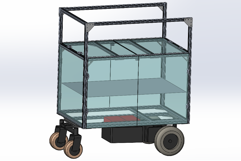 Figure 1: Conceptual design for
electric vehicle with floor removed to show
attachment details.
Background
Introduced by General Motors in 2021, BrightDrop is a modern
effort to reimagine first to last mile delivery operations
through the use of electric vehicles. This project is focused
on the "last 100 miles" of delivery; that is, moving packages
safely and efficiently from a delivery truck to the customer's door.
Our vision, in collaboration with the team from General Motors
is to design and build a modular, electrified vehicle for
transporting packages and lab equipment around the Duke
engineering campus. The final design for the vehicle
is shown in Figure 1. The immediate use case for our design is
to help the engineering lab staff at Duke University.
The minimum design criteria for the device as specified by
the client are listed below in Table 1.
Table 1: Design Criteria
| Criteria | Target |
|---|---|
| Payload weight | ≥ 100 lbs |
| Package size | ≥ 30" x 24" x 24" box or 8" x 8' tube |
| Package capacity | ≥ 2 |
| Maximum speed | ≥ 3 mph |
| Range | ≥ 1/2 miles |
| Battery lift | ≥ 1 hour |
| Security | Use of device requires key or secure code |
| * As specified by client | |
Key Design Features
The body of the cart was designed with two hinged doors on the front and back faces and two hinged doors on the top face. These will allow easy access to the interior of the cart from either the front or the top of the device. There is one removable shelf in the middle of the cart, which can be adjusted to different heights as needed. The overall dimensions of the cart body, shown in Figure 2, were chosen with consideration to typical doorway and elevator dimensions. Another image of the cart body is shown in Figure 3 with all of the doors in an open position. In terms of material selection, the frame of the cart body is constructed from 80/20 aluminum T-slot beams and the side panels are cut from acryllic.
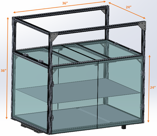 Figure 2: Cart body with basic dimensions.
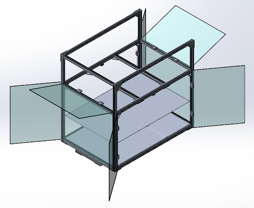 Figure 3: Cart body with all doors open.
The base of the vehicle, which includes the powertrain and the wheels, is made from a modified electric wheelchair. A CAD model of the wheelchair base is shown in Figure 4, with modified areas highlighted in red or blue. The section highlighted in blue will be sawed off to allow the interior of the cart base to be flush with the attachment pole. The back wheels, highlighted in red, will be separated from the rest of the chassis and attached to the rear end of the cart body. This will involve using an angle grinder to cut through two small welding points and reattaching via nuts and bolts to the 80/20 frame of the body. Extending the wheelchair chassis will increase the length of the wheelbase, improving the storage capacity and stability of the vehicle.
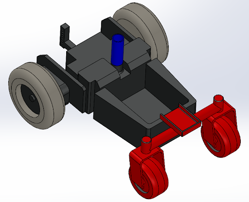 Figure 4: Wheelchair base with modified areas highlighted.
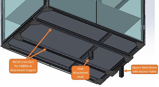 Figure 5: Cart body shown from below with labeled components.
Control Flow
The proposed control flow diagram for the vehicle is shown below in Figure 6. Starting with the inputs, two single-axis joysticks were selected along with a trigger for the electromagnetic brakes. These input modules will be mounted to the handle of the device, with one joystick controlling forward/reverse motion and the other controlling left/right steering. Signals from the input modules will be fed into an Arduino UNO and transformed into control signals for the motor controller. The selected controller is a 40A dual-motor controller from Pride Mobility. In this module, the control signals will be processed to determine the required speeds of each motor to achieve the desired motion and the motors will be actuated accordingly. For powering the circuit, the 24V power supply will be connected directly to the motor controller and will be connected to the Arduino via a 24V/5V DC step down converter.
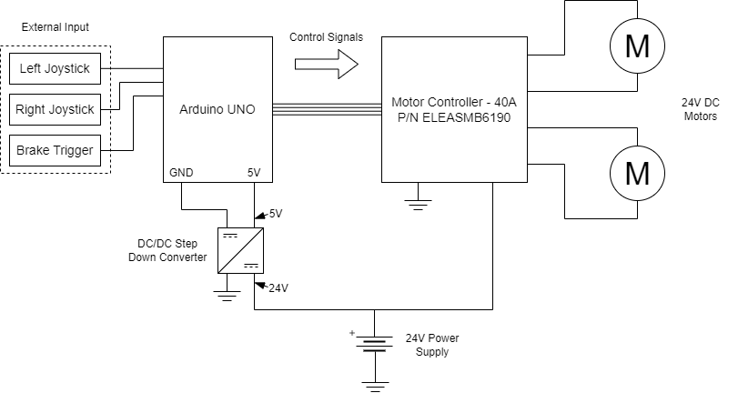 Figure 6: Control flow diagram for electric vehicle.
Future Work
The next steps in developing the proposed electric vehicle are to order the selected components and begin construction. The team plans to first focus on achieving successful motion control of the vehicle using manual inputs. Once the device is built to support the required payload as specified in the design criteria and can be controlled manually, the minimum design criteria will be satisfied. At this point, the team has selected a number of additional features to pursue.
For carrying long, cylindrical packages, the team plans to develop specialized holders to secure the packages and prevent unwanted motion. These holders should be designed with consideration of the carts overall profile for fitting through doors and hallways.
Additionally, the team hopes to introduce more autonomous features to the vehicle for improved usability. In general, this will involve adding visual and proprioceptive sensors to the vehicle to serve as inputs to the Arduino microcontroller. Some features that the team has prioritized are automatic braking, incline detection, and obstacle avoidance. The ultimate goal would be for the device to follow a user at a specified distance while autonomously navigating turns, corners, inclines, bumps, and any other static or moving obstacles. Safety would be of utmost importance in this pursuit, so the team would set high standards for the awareness and reliability of autonomous systems.