Projects > Magnetic Levitation Device
Magnetic Levitation Device
October 2020 - November 2020
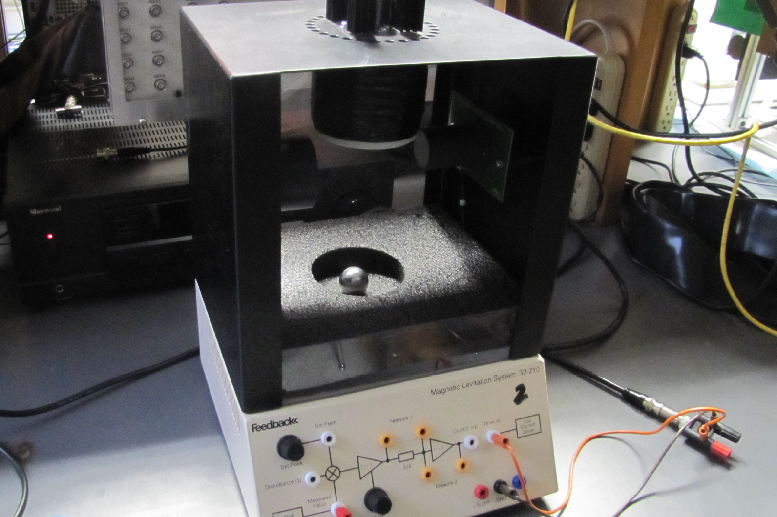
 Figure 1: Magnetic levitation system employed in this project.
Background
This goal of this project was to model a magnetic levitation device
and to design and simulate a proportional-integral-derivative (PID) controller
to modulate the height of a metal ball in the system. The system
used, shown in Figure 1, is the Magnetic Levitation System MLS 33-210 manufactured by
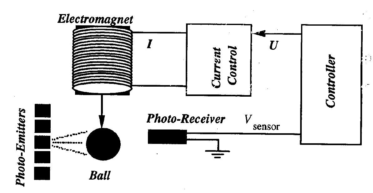
Feedback Instruments Ltd. This unit is comprised of an electromagnetic wire coil,
a photo-emitter, a photo-receiver, and a front panel.
Ports on the front panel can be connected to an NI Data Acquisition
Board to receive position data collected by the photo-sensing unit
in the form of a voltage. Another input port on the
front panel allows an external controller to vary the
current to the electromagnet through a controller output voltage.
A diagram of this system is shown in Figure 2.
 Figure 2: A simplified diagram of the magnetic levitation system.
Our controller was modeled in LabVIEW with adjustable
inputs for the proportional, integral, and derivative gains.
In modeling the system, we determined the plant transfer function
and gathered the relevant system characteristic. To
systematically obtain the optimal gain values, we began
by selecting a proportional gain for which the system was
stable. We then introduced a derivative gain value and tuned it
until the system exhibited a reasonable damping ratio and
acceptable values for settling time and percent overshoot.
Finally, we introduced an integral gain value to eliminate steady-state
error and tune the rise time. After making slight modifications
to all three gain values, we were able to achieve all
of the desired performance specifications. The desired performance
specifications along with the actual values achieved in
simulation are given below in Table 1.
Table 1: Performance Specifications
| Specification | Desired Value | Actual Value | Accepted? |
|---|---|---|---|
| Damping ratio, ζ | 0.675 < ζ < 0.707 | 0.705 | YES |
| Settling time, Ts | Ts < 0.5 s | 0.265 s | YES |
| Rise time, Tr | Tr < 0.1 s | 0.0206 s | YES |
| Percent overshoot, PO | PO < 10% | 4.40% | YES |
Testing
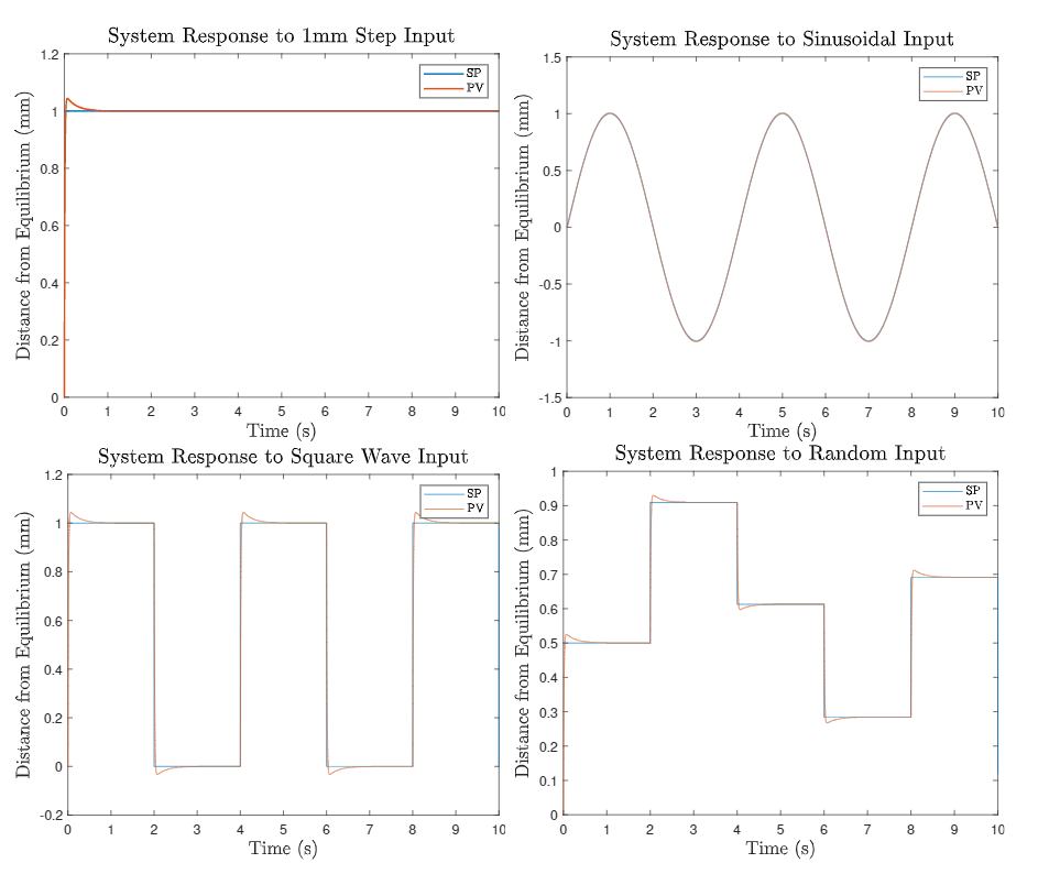
After tuning the controller to meet the given specifications, we tested the design in a laboratory setting. Four different input signals were to be tested: a step input, sinusoidal wave, square wave, and sequence of random step inputs. Plots of the system response in simulation to these various inputs are shown below in Figure 3. In the real testing environment, the ball levitated successfully in all four cases without the need for any additional tuning. The system also proved robust, since the ball was able to levitate with a metal bolt also levitating beneath it.
 Figure 3: Plots of the process variable (PV)
and setpoint (SP) using the tuned PID controller for a step input (top left),
sinusoidal input (top right), square wave input (bottom left), and
random input (bottom right).